New Parts

September 5th, 2006

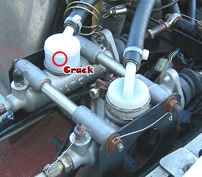
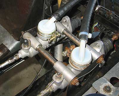
 The parts came in for the Tilton master cylinder.  So I spent Labor Day removing the temporary master cylinder reservoir I borrowed off the RGM and installing the new remote reservoir adapter.  I was pleased with the E-Bay store Race Basics (http://stores.ebay.com/Race-Basics) I’ll be turning to them first when it comes to braking and other sundry components in the future.

 Installation wasn’t a big deal.  Cleaned out the Master cylinder, and blew the connecting hose and remote reservoir clean with compressed air before I test fit everything.  Once together I ziptied the hose ends and secured the nylon remote reservoir adapter with the new clamp I picked up as well.  I wish I’d bought an extra clamp, as the one on the other master cylinder looks pretty furry.

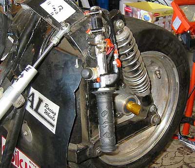
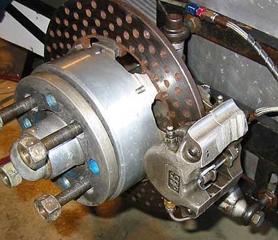
Once that was done I went ahead and started the process of bleeding the entire braking system.  This is not an easy task.  On race calipers each piston has it’s own bleeder.  That’s four bleeders on each wilwood caliper, and two bleeders on the SRP caliper.  Think about that the next time you’re whining about the three bleeders on your bike.  The rear wheel isn’t too bad, as I can get to all four bleeders on the caliper with the caliper mounted.  But the outboard wheel has to come off, and the front wheel has to come off and the wheel be removed from the hub/spindle assembly to allow full access to the wilwood caliper.  I have a decent vac-bleeder so the actual bleeding job isn’t horrible.  The first thing I noticed when I popped the outboard wheel off and really examining my SRP caliper is that it was mounted upside down.  The bleeders were on the bottom, and the crossover tube was on top.  It would be impossible to bleed all the air out of the caliper unless I took the caliper off and flipped it over while I was bleeding it.  Now this would suck every single time I wanted to bleed the brakes.  So the long term solution is to simply yank the bleeders from the bottom of the caliper, the crossover tube from the top, and swap them.  This took some time and finess as things were, er… cemented in place by grit, dirt, and time.  Lots of cleaning, a little heat, and very careful application of force got all the parts out in good condition.  I blew out the inside of the caliper body with compressed air before reinstalling the bleeders and crossover tube with a bit of threebond on the threads.  Once things were in place and the caliper was mounted and safety wired, I filled it with fluid using a neat jedi brake trick I learned helping Wade with his brakes at Fernley.  Once that was done I ran 1.5 bottles of good DOT3 through the entire rear/outboard braking system to ensure no air anywhere at all and buttoned it up.

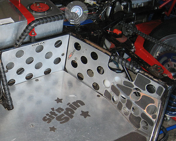
I finished with flushing and bleeding the front system, reassembling and safety wiring everything again.  All mushyness is gone from the brake pedal now.  I didn’t touch the balance bar or any of the bias on the master cylinders.  If it’s not broke, don’t fix it.  Since I had time left, I decided to yank the secondary AutoMeter water temp gauge from under the CBR1000RR dash in the drivers cockpit and relocate it to an area in the passenger compartment where I could see it.  There is a working built-in temp gauge on the CBR1000RR dash, and Sarah is much more focused on keeping the rig on the road than she is the innerworkings of the powerplant behind her.  It makes sense to assign that task to me.  I couldn’t find anything in the rulebook that said no to having any indicatiors or gauges in the passenger compartment, so I mounted up the AutoMeter next to the low oil pressure ‘turnsignal’ indicator light.  I fired the rig up and let it get to 160 to confirm both temp gauges were roughly in sync.  The CBR1000RR stock temp gauge picks up in the engine, and the block runs about 6 to 10 degrees cooler initially since it takes awhile for all that metal to come up to operating temperature.  The AutoMeter gauge shows a more accurate reading of the actual coolant temperature since it’s pickup is right in the filler reservoir assembly.  I’m happy with this, and I’ll feel much more comfortable at the track knowing that now I have an estimate of what the engine health is.

Testing…

September 2nd, 2006

Sarah and I went out to the Westside Proving Grounds to test the new shifter assembly and twist throttle.  The twist throttle is spot on, but the shifter assembly length will need some adjustoment and fine tuning for Sarah.  Not a big deal.  The brakes proved to be an issue, they’re spongy a bit… something that will get fixed when the parts for the Tilton finally arrive.  We couldn’t find a happy medium in brake pedal placement for Sarah’s foot.  One click on the spline back, it’s too far back… she can’t put enough pressure on the pedal to lock up the wheels.  One click forward, it’s too close… she can’t get her foot on the brake pedal without hanging up.  I’m thinking 99% of this has to do with the crappy combat boots she wears.  They have big boxy toes and fat waffle soles.  If she had a real pair of roadracing boots we could leave the brake lever forward and it’d probably fit her perfectly.  All in good time.  Next time we go testing I’m going to have her wear the thinnest shoe she has on her braking foot to see if it makes a difference.  it’s that, or I fabricate a new brake pedal.  Here’s some shots from our goofing off via Eric.


Oh, and inital tests of the asspuck show it’s placement perfect.


Ass Pucked

September 1st, 2006

Picked up my suit from Helimot today.  I’ll let the picture do the talking.

Always check Ebay first…

August 30th, 2006

So I noticed brake fluid leaking from one of the Tilton master cylinder literally after I’d cinched the last tiedown on the CSR the afternoon before we left for Reno/Fernley.  It turned out that one of the nylon remote reservoir feed caps on the master cylinder had decided that would be an excellent time to develop a crack and start pissing fluid.  Better there in the driveway than halfway around the track I guess.  As I found out, this isn’t a part Winchester Auto or Kragen just have laying around.  And it’s not a part you can fix with JB weld and epoxy no matter how hard you cross your fingers.  After much panic I discovered that the nylon reservoir on the RGM was exactly the same size as the one on the CSR.  So the RGM was cannabilized and the brakes on the CSR bled in the dark the night before we left for Reno with the rig strapped to the trailer.

Now that things have calmed down I figured I’d pick up replacement cap and a spare for the toolbox.  Tilton as it turns out does not sell direct, but they’re happy to give you a list of resellers in the middle of assfuck-nowhere who do.  So I place a call to the closest guy in the interest of shipping charges.  He takes his sweet time calling me back only to tell me it’s a ‘special order’ part, and to top it off it’s 10 bucks a pop, and there will be shipping to boot.

Yeah, let me get back to you on that…

So I jump on Ebay, and sure enough, there is exactly what I need for Three Dollars and Seventy-Five Cents New in the Box.  I bought two. 

http://cgi.ebay.com/ebaymotors/ws/eBayISAPI.dll?ViewItem&item=270015006879

Shift Linkage

August 26th, 2006

The shift linkage/assembly has always been a pain in the ass.  The way JG set up the rig it was quite literally built for him, and nobody else.  By sheer luck Sarah was able to get in the rig and mostly use the shifter with nothing but minor adjustment.  But if we wanted faster/smoother shifts it was going to have to be fine tuned and all the slop taken out of things. 

The way the current setup works your foot goes into a toebox that hangs from a rather loose heim joint.  The toebox is a bit wide so there is too much free play between your boot and the upper/lower bar of the toebox.  From the toebox you have a non-adjustable pushrod with heim joints on either end that connects to a 90 degree bellcrank.  From the bellcrank we go up to the stock shifter pushrod and to the stock shifter bellcrank on the end of the shift shaft. 

The first problem I noticed was that the stock bellcrank on the shift shaft was not in the ideal position for optimial up/down leverage on the shift shaft.  It was about four cogs too high on the spline, or about 45 degrees.  This put the direction of force from the stock pushrod too far on the inside of the bellcranks direction of travel.  This was easily fixed by just dropping the bellcrank down till it made a 90 degree angle with the stock pushrod.

The second problem was the non-adjustable pushrod between the toebox shifter and the lower bellcrank.  This was quickly solved by taking the stock part to Orchard Supply, buying some Allthread, a couple heim joints, and jam nuts.  I threaded one heim joint all the way onto the end of the Allthread and set the stock linkage next to it.  I made an index mark 1.5 inches shorter than the stock pushrod, and took my dremel to the Allthread.  Once I had it cleaned up and quickly test assembled on the CSR with all new fastners it was obvious the new pushrod would allow more than enough adjustability.  I could drop it back enough for my foot to knee length now if I wanted to.

Lastly was taking all the slack out of the top heim joint that the toebox shifter hangs from.  I simply replaced all the old fastners and furry washers with new hardware and some nice thick powdercoated washers I had in my parts bin.  This got rid of nearly all the sloppy feel in the shifter while leaving just enough to allow pivoting and lateral movement of your foot without bumping the bike out of gear.

The original non-adjustable pushrod


The adjustable replacement


Race One ~ Fernley

August 20th, 2006

 Sarah and I did fairly decent our first weekend out with the CSR.  Our goal was to simply finish a race, bring the CSR home intact, and not die in the process.  Something we managed to accomplish despite the triple-digit heat and both of us being not in the ideal physical condition.  Don’t get me wrong, we’re not lethargic couch potatos, but it turns out this sport demands a far higher level of physical conditioning than regular two-wheel motorcycle racing.  I had to lift poor Sarah from the cockpit at the end of the race on Sunday.  But we finished, 16th out of 17 rigs.  We were not last, and we didn’t DNF.  I wore a hole in the ass of my leathers from dragging my butt through left hand corners.  Helimot is repairing my suit and slapping some velcro on the left asscheek so I can throw a puck on there for ass-sliding goodness.

 We did find out that while the trigger-throttle works for Jean-Guy, it sucks for everybody else.  Two laps with the index finger trigger throttle and your hand starts to cramp up pretty bad.  Not to mention it’s pretty much impossible to modulate one inch of throttle pull with one finger and turn left at the same time.  I figured Sarah was just not used to the throttle yet when she was complaining about it being hard to use, so I took the rig out early Sunday with Wade on the platform for a few laps.  Yep, my hand cramped.

 So when we got home I pulled the assembly and with a bit of careful filing around the starter button bracket was able to slot in a BBR single cable throttle assembly that Jocelyin sold me.  They don’t come with cable slack adjusters, as those are built into the Honda 50 throttle cables, but I found that a standard double banjo brake bolt threads right in.  So in a fit of ingenuity I cut the head off the banjo bolt, slotted it to allow it to slide over the cable, and countersunk one end to allow the cable ferrule to recess snugly.  With the addition of a locknut, I had a slack adjuster.  I lubed the assembly up and hit all the fastners with RTV once everything was assembled.  Test runs so far feel good.  Won’t know till we’re on the track proper.